Note:
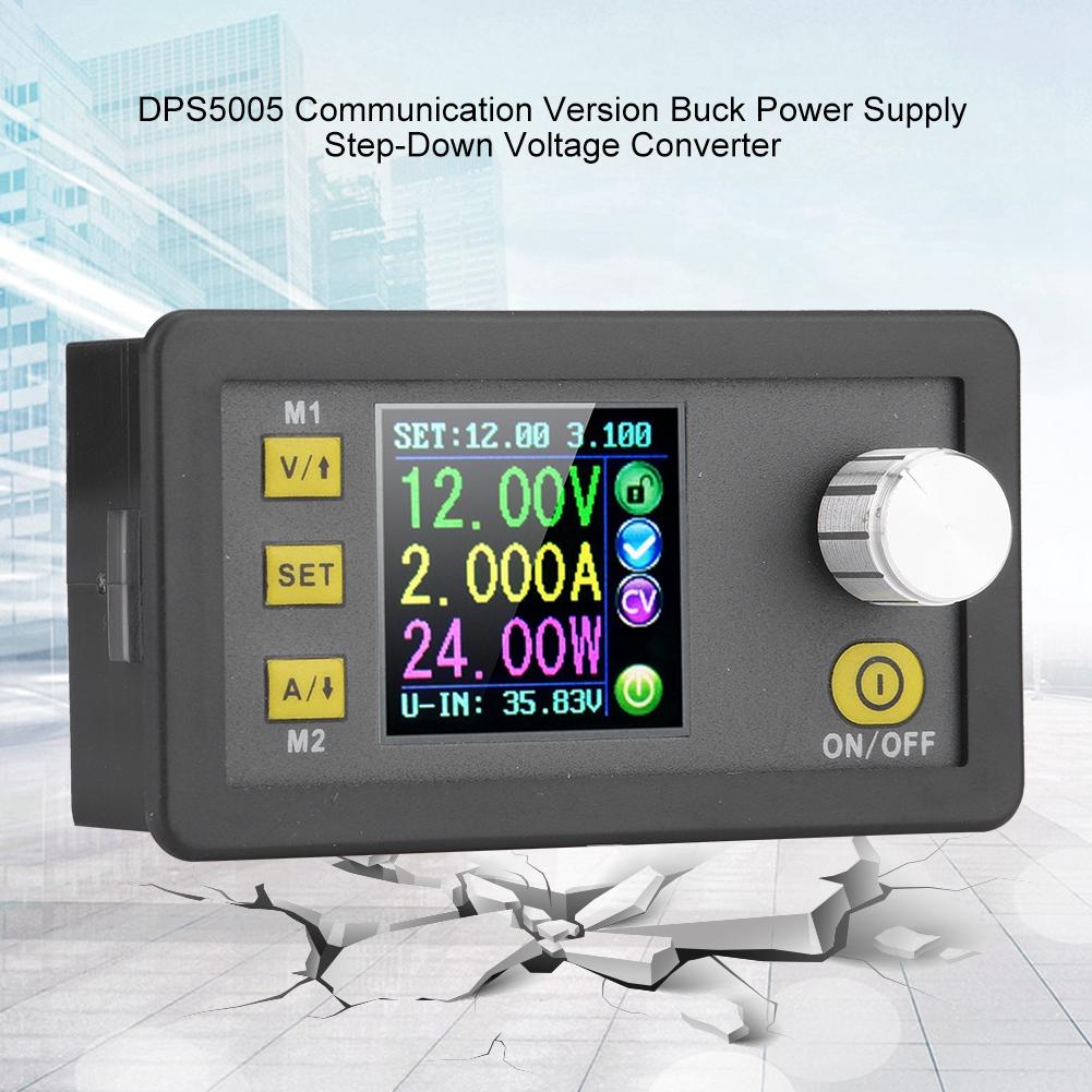
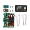
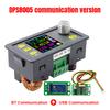
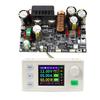
1.This is DPS3005
DPS5005
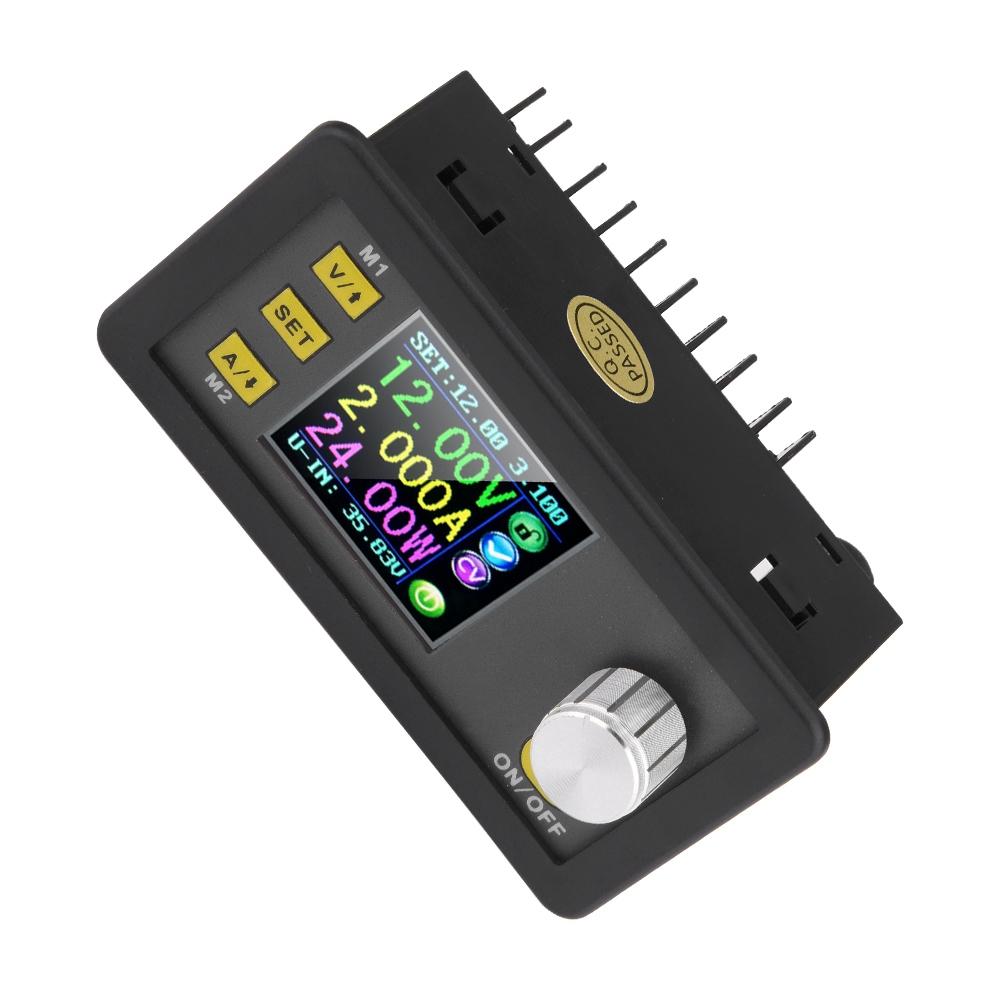
communication version, there is a communication interface on the back.
2.USB + Bluetooth means: DPS3005
DPS5005
+ USB communication board+ Bluetooth communication Board
A: We have the file for upper computer installation and software, you can contact us.
B: Upper computer installation, connection by USB and Bluetooth video: you can go to RD tech youtube channel to check
3.
DPS3005 DPS5005
have same functions, only the
technical parameters are different,for example, voltage, current ,etc.
Very important:
1.Before buying this product, please download the upper computer software and test, if it fits your computer , you can buy
2. the upper computer only support For Win7 and above
Features:
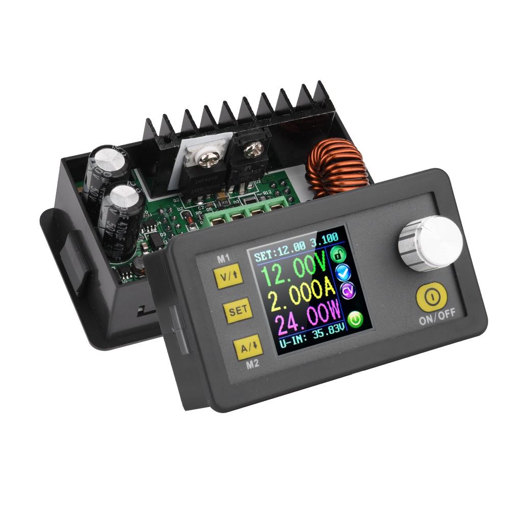
The constant voltage and constant current programmable control power supply module put the collection of analog integration and digital control functions in one.
This module has power down stored function and can store 10 groups preset value.
And it also has the function of extracting quickly two groups stored value.
Compared with the traditional analog power supply, it is more convenient to quickly extract the voltage or current required.
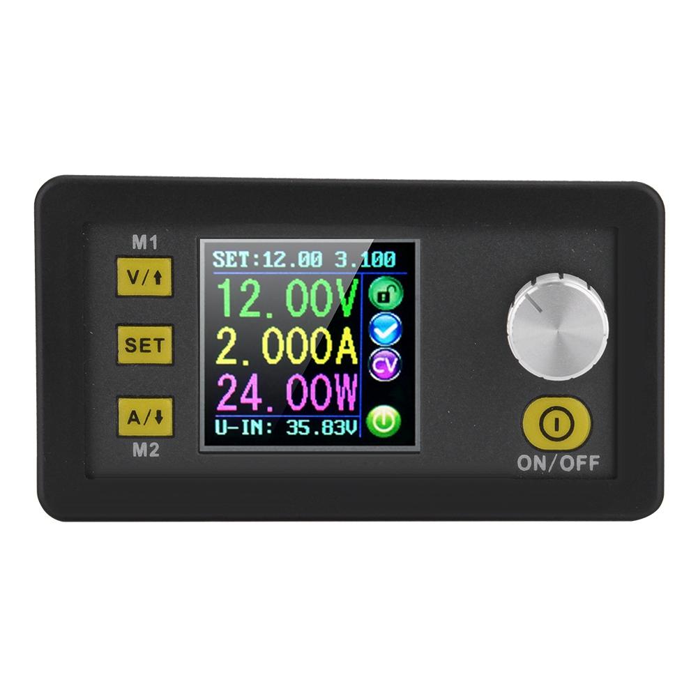
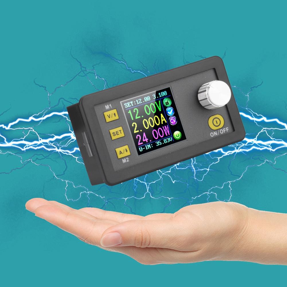
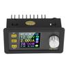
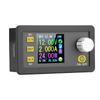
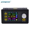
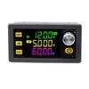
LCD display on the module has the function digital voltmeter and ammeter. You can view the preset voltage, input voltage, output voltage, the preset current, output current, output power, etc.
On the output state remind area, you can see that output opens or not, the state of constant voltage and constant current, output is normal or not, the key is locked or not, and the current data groups that is being used.
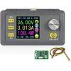
On the setting data interface, you can adjust over voltage value, over current value, over power value, data set and LCD brightness.
This module has many advantages, small size, advanced function, good visual effect, high operability, high precision, being used independently, being inset into the device and been widely applied.
Specification:
Model(Optional)
DPS3005
DPS5005
Input
voltage
6.00 40.00V
6.00 55.00V
Output
voltage
0V 32.00V
0V 50.00V
Output
current
0 5.000A
0 5.000A
Output
power
0 160.0W
0 250.0W
Voltage
resolution
0.01V
0.01V
Current
resolution
0.001A
0.001A
Size
80*44*45mm 3.1*1.7*1.8in
Weight
Approx.138g 4.9oz
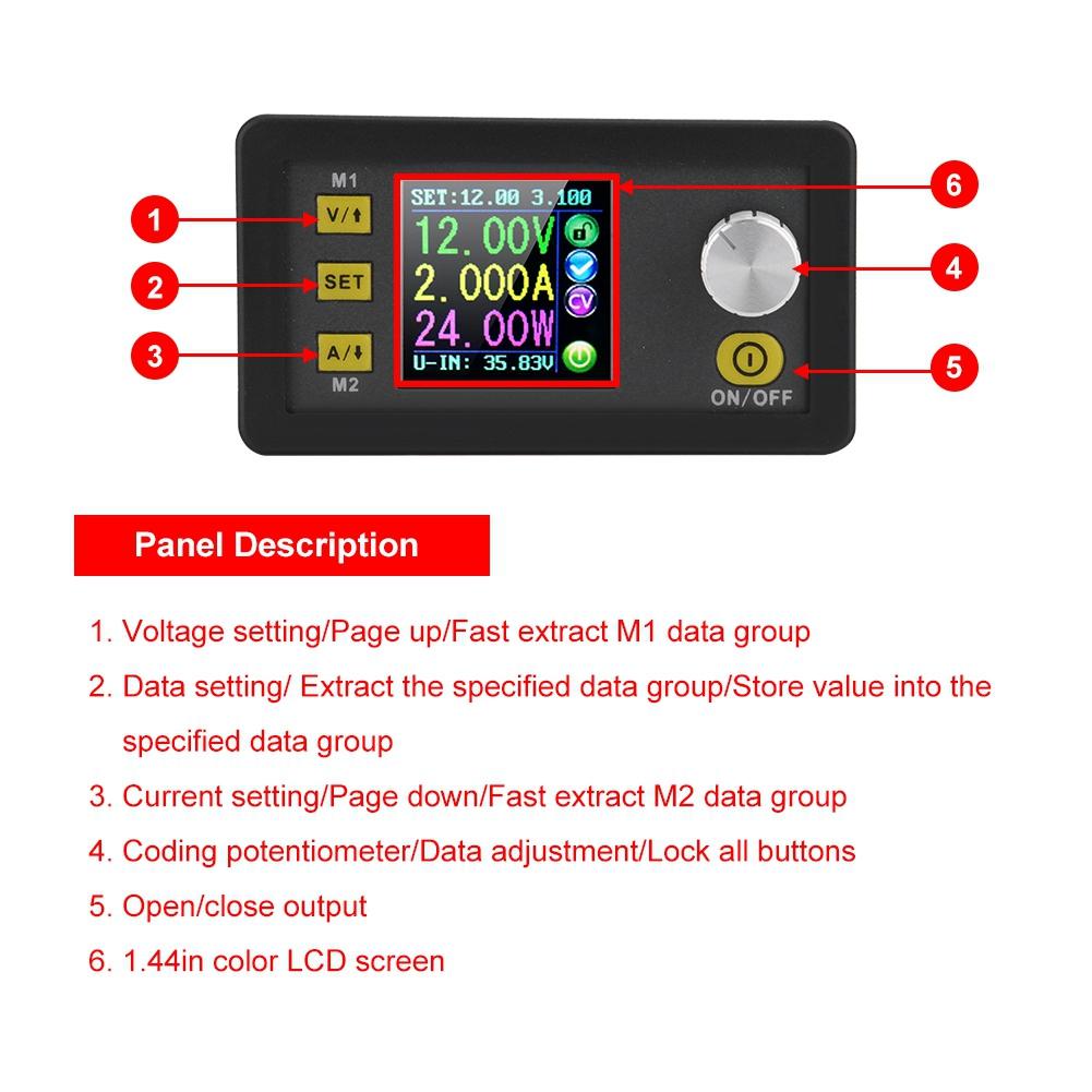
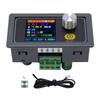
Connection description
IN+: Input positive, IN : Input negative:
OUT+: Output positive, OUT : Output negative
Note: Input voltage range is DC 6 40V and 40v is the limit voltage; please leave a room to use. Or else it will be burnt. The input must be DC power supply, not AC 220V, or else it will be burnt too. Though this module has reverse connection protection and output short circuit protection, you can muse be in strict accordance with connection description to connect. If you connect the supply power with output, the module will be burnt.
Operating instructions
When connect the power supply, the screen shows welcome window firstly and then comes into main interface.
Set the output voltage and output current on the main interface.
Press V UPkey shortly, you can enter into voltage setting status. Then press the coding potentiometer, and then enter to adjust the numerical value. Press coding potentiometer to enter into the status of adjusting the numerical value you want to adjust. Turn coding potentiometer to adjust the numerical value. Turn by clockwise rotation to increase the numerical value; Turn by counterclockwise to decrease the numerical value. If you want to exit adjusting the numerical value, press shortly V UP. In the same time the preset value will be stored. Or you can do nothing in one minute, the status will be automatically existed and the preset will be stored too. You can press A Downto set the output current by the same way.
Set the data on the data setting interface
On the main interface, you can press SET key shortly to enter into data setting interface. On the data setting interface, press shortly V UPor A Down to page up or page down to U SET or I SET, and then set the output voltage and output current by same way used in the main interface .
Set the protection value.
Page up or page down to S OVP, S OCP or S OPP place to set over voltage value , over current value and over power value correspondingly; when the value is up to the setting value, output will be closed. And then press shortly the coding potentiometer to enter into the status of adjusting the numerical value you want to adjust. Turn coding potentiometer to adjust the numerical value. If you want to exit adjusting the numerical value, press shortly SET key.
Adjust the brightness of screen.
Page up or page down to B LED, and then press shortly the coding potentiometer to enter into the status of adjusting the brightness of screen. Turn coding potentiometer to adjust the numerical value you need. If you want to exit adjusting the numerical value, press shortly SET key. There are six brightness levels of LCD screen, 0 5 level. Rank 0 is the darkest; rank 5 is the brightest. You can choose what you like.
Data setting and store the specified data group.
Page up or page down to M PRE, and then press shortly the coding potentiometer to enter into the status of choosing the data groups. Turn coding potentiometer to choose the data group you need to view. Then the data group you need will be displayed. And then press the coding potentiometer to enter into status of changing output state. Turn coding potentiometer to choose ON or OFF. When choose ON, the data group is extracted and the output status remain the same. When choose OFF, the data group is extracted and the output is closed. If you want to exit choosing data set, press shortly SET key. Then press shortly V UPor A Down to page up or page down to other place to adjust the data you need. After data setting done, keep pressing SET key more than 2s, all the data you set are automatically stored into the specified data group. In the same time, you can see the group number on the right of screen. At last you can press shortly SET key back to the main interface.
Set default boot open or close output
Page up or page down to S INI, and then press shortly the coding potentiometer to enter into the setting status. Set ON, default boot open; set off, default boot close.
Function description:
Open or close the output.
You can press ON OFF key to open or close the output on any interface.
Lock the button to avoid wrong operation.
On the any interface, you can keep pressing coding potentiometer more than 2s, all buttons are locked. You can see the key lock icon on the right of screen. If you want to unlock all buttons, keep pressing coding potentiometer more than 2s, all buttons are unlocked. The key unlock icon will be displayed on the right of screen.
M0 M9 ten groups data group
M0 group is the boot default data group. When you extract the data group you need, this data group will cover M0 data group and be automatically stored on M0 data group.
Extract Shortcut storage data group M1 or M2.
On the main interface, keep pressing V UPor A Down more than 2s, you can extract Shortcut storage data group M1 or M2 quickly. In the same time the corresponding data group number will displayed on the right of the screen.
Extract the specified data group.
On the main interface, keep pressing SET key more than 2s, the sequence number of data group will be displayed on the right of the screen, you can turn coding potentiometer to choose data group you need. And then press shortly SET key, you can extract the specified data group you need.
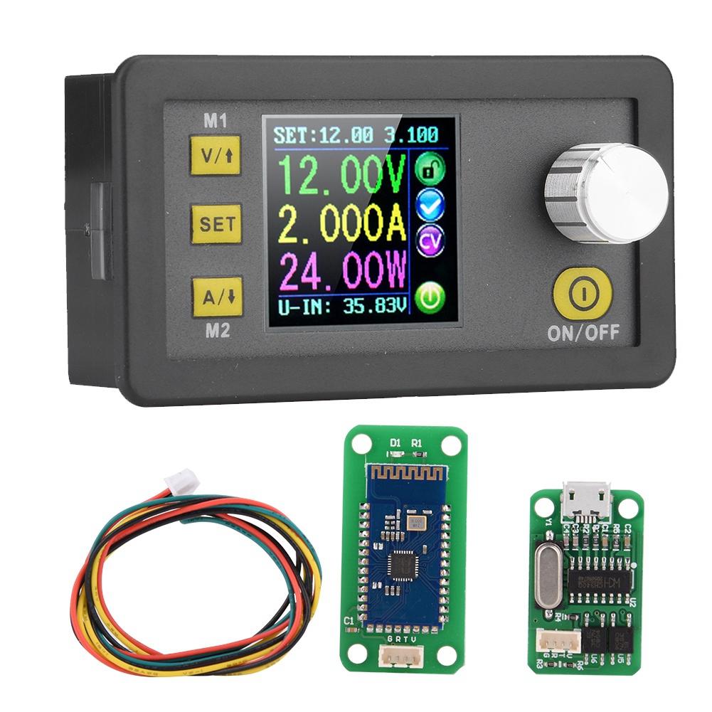
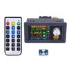
Package list:
1 x Step Down Module
1 x blueteeth board
1 x USB board
1 x communication cable