Describe:
Logic Operating Voltage: (Vdd)+4. 8V^ +5. 2V
Display: black characters on a yellow background
LCD drive voltage: (Vdd-Vo) +5V
Operating temperature: (Ta)-20° C~+70° C (wide temperature)
Storage temperature: (Tsto)-30° C~ +80° C (wide temperature)
Operating current: (except backlight) 1.7mA (max)
Operating current: (backlight) 24. 0mA (max)
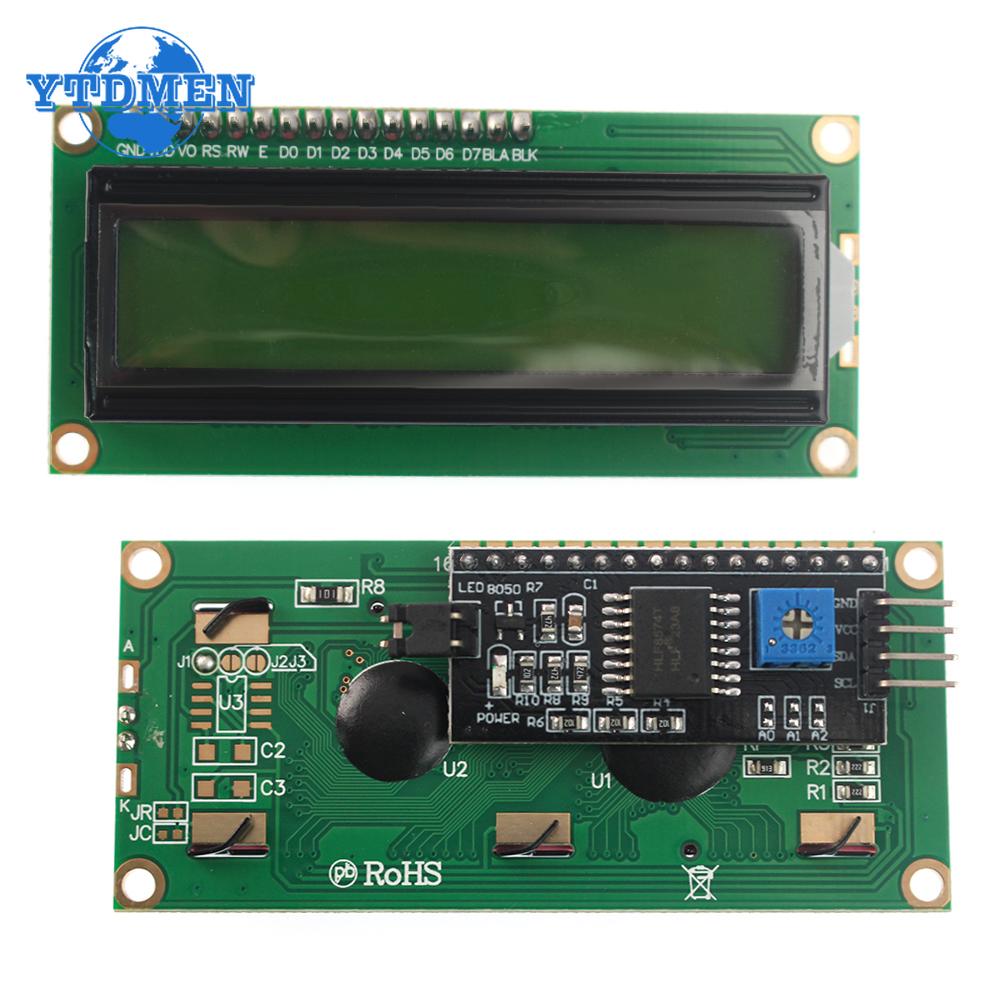
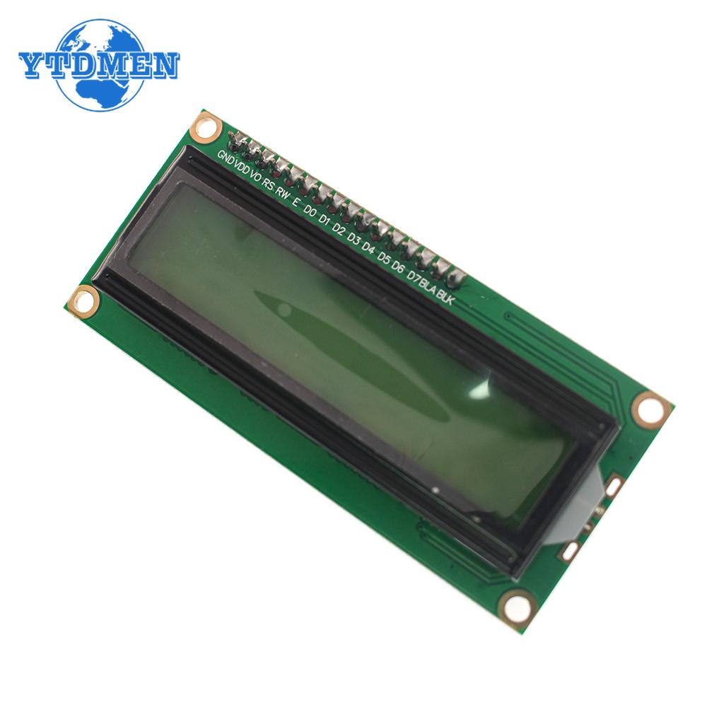
pin
No. Symbol I/0 Pin Description
1 VSS power ground (0V) ,
2 VDD power supply positive terminal (5V)
3 VO LCD drive voltage input terminal
4 RS command/data selection signal
5 RW Read and write selection signal
6 E Enable signal
7 DO I/0 Data 0
8 D1 I/0 Data 1
9 D2 I/0 Data 2
10 D3 I/0 Data 3
11 D4 I/0 Data 4
12 D5 I/0 Data 5
13 D6 I/0 Data 6
14 D7 I/0 Data 7
15 BLA LED+ (5V)
16 BLK LED- (0V)
Pin 1: VSS is the ground power supply.
Pin 2: VDD is connected to 5V positive power supply.
Pin 3: VL is the contrast adjustment terminal of the liquid crystal display. The contrast is weak when connected to a positive power supply, and the contrast is limited when it is grounded. When the contrast is too high, a "ghost image" will occur. You can use a 10K potentiometer to adjust the contrast.
Pin 4: RS is the register selection, select the data register when it is high, and select the instruction register when it is low.
Pin 5: R/W is the read and write signal line, the read operation is performed at high level, and the write operation is performed at low level. When the common low level of RS and R/W is low, the command or display address can be written. When RS is low, R/W is high, and the busy signal can be read. When RS is high, R/W is low.
Data can usually be written. .
Pin 6: The E terminal is the enable terminal. When the E terminal jumps from a high level to a low level, the liquid crystal module executes the command. .
Pin 7^14: D0~D7 are 8-bit bidirectional data lines.
Pin 15: The positive pole of the backlight.
The 16th foot: The negative pole of the backlight source.
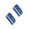
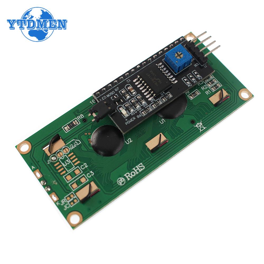
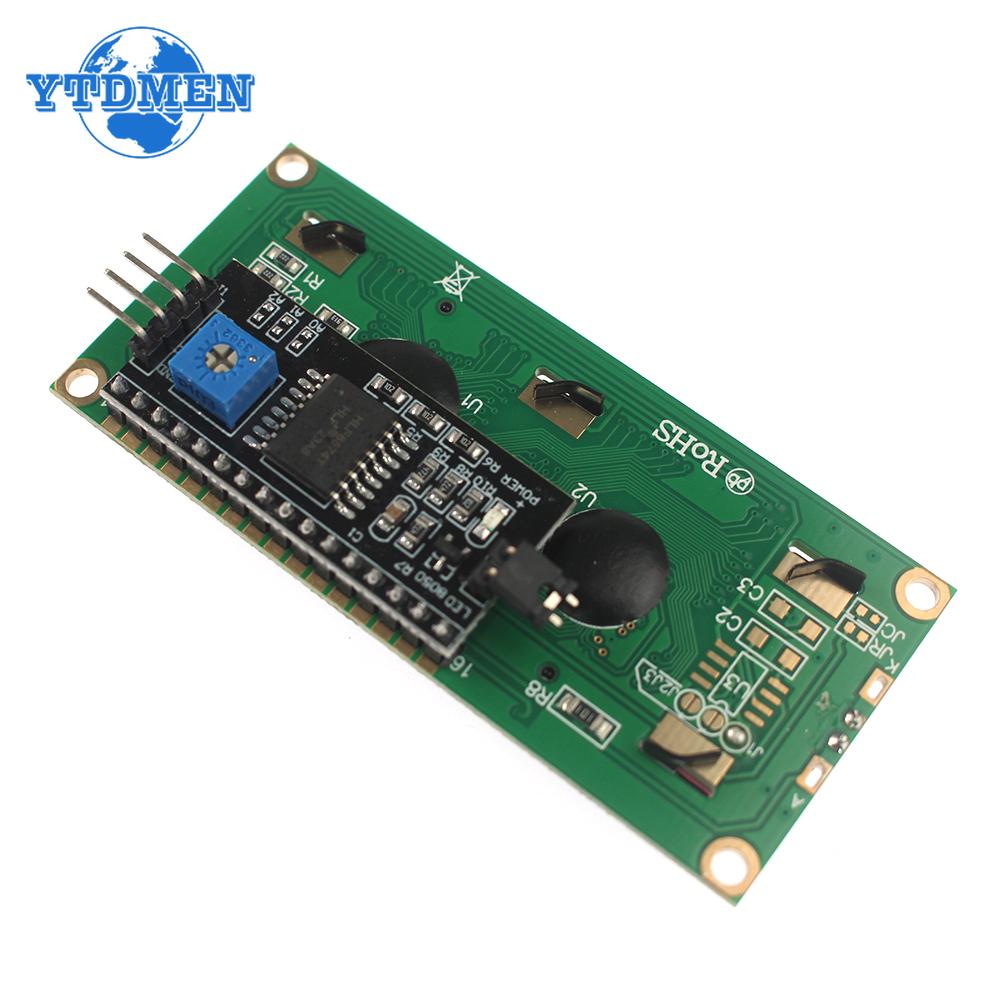
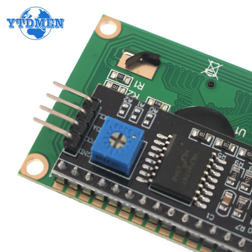
Adapter board
Supply voltage: 2. 5-6V
Support 12C protocol, with backlight, you can set whether to have backlight through the jumper cap, plug in the jumper cap to have the backlight, and remove the jumper cap to remove the backlight. The contrast can be adjusted by the blue potentiometer, the magic hour hand is strong, and the counterclockwise is reduced by 5. The potentiometer is set to i on the top, which is convenient for customers to adjust for their own use. Device address: can be modified by short-circuiting A0IA1/A2.
wiring
GND: negative pole of system power supply
VCC: system power positive
SDA: IIC data cable
SCL: IIC clock line


 No-delivery refund